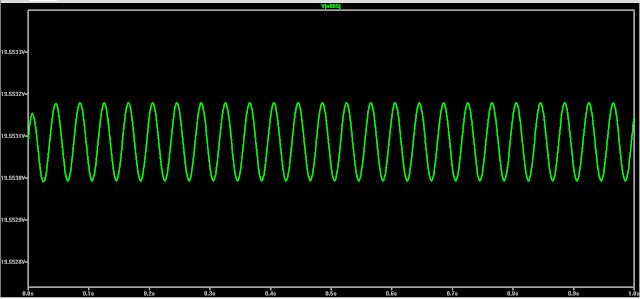
During the testing phase we discovered that when we vary the R12 resistor to a very low value, the 2N3053 transistor gets very hot and this takes so much current from the power supply. Below is the simulation output when we vary the resistor to 1 ohm.
Figure 9: Output voltage when R12 is at 1 ohm.
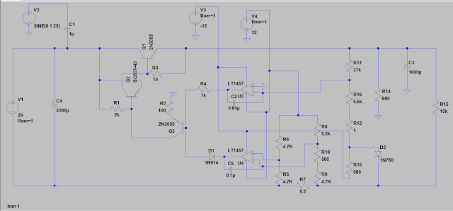
From the figure, it can be seen that the waveform does not meet our required circuit design which is a linear regulated power supply. This was a big issue because we needed to regulate the voltage from zero to its maximum value. As we increase the resistance of R12 resistor we discovered that at certain resistance we got a linear output. So we decided to add a resistor in series with the variable resistor R12 of value 6.5K ohms. Below is the simulated waveform and the edited circuit,
Figure 10: The new circuit to be built with the required output.
Figure 11: The maximum output voltage at low R12 resistance
The above circuit in figure 10, is the circuit to be built, since there are no more errors in it. The circuit will be transferred into a veroboard to be soldered and tested in reality. The above simulation is right, but however in reality most of the component to be used are not exact so there might be little errors.


No comments:
Post a Comment